The LVDT stands for Linear Variable Differential Transformer. It converts the Linear motion into an electrical signal using an inductive transducer. Due to its superior sensitivity and accuracy over other inductive transducers, the LVDT is extensively used in many different fields. For measuring linear distance, the linear variable differential transformer (LVDT) is a precise and trustworthy tool. Today, LVDTs are used in computerized manufacturing, robotics, avionics, and machine tools, combining research facilities, high-level analysis, and analysis to detect damage caused by massive rock deformation or other movements in the subgrade of old buildings or structures. physical structure. One try. This method is used to try to detect failure in concrete slopes and warn or correct the condition. One of the special problems with historical buildings is that they can easily be damaged by small deformations in the long run.
Table of Content
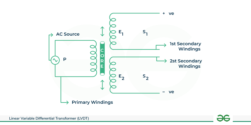
LVDT stands for Linear variable differential transformer. It is one of the major types of Inductive transducers. LVDTs are considered the most accurate inductive sensors that measure displacement according to the polarity and magnitude of the net induced electromotive force (EMF) and are therefore also known as linear variable displacement sensors.

Simple LVDT Diagram
Linear Variable Differential Transformers (LVDTs) can be of many types based on their construction, size, and specific applications. Here are some common types:-
There can be many more LVDTs based on the requirement of the application like High-Temperature LVDTs, Digital LVDTs, or Heavy-Duty High-Frequency Response LVDTs.

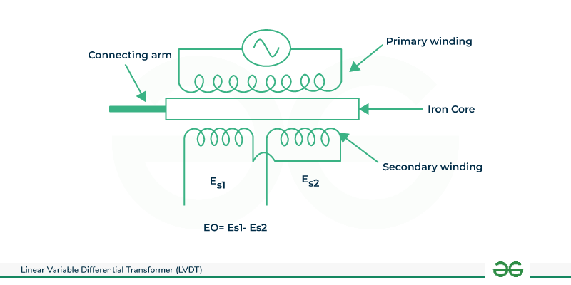
LVDT in the null position
The transformer and LVDT share a similar construction. It consists of one primary winding(P) and two secondary windings (S1 & S2). The primary and secondary windings are bounded by a hollow cylinder, known as the former. The primary winding is at the center and the secondary windings are present on both sides of the primary winding at an equal distance from the center. Both the secondary windings have an equal no. of terms and they are linked with each other in series opposition, i.e. they are wounded in opposite directions, but are connected in series with each other.
The entire coil assembly remains stationary during distance measurement. The moving part of the LVDT is an arm made of magnetic material.
The working of LVDT is based on Faraday’s law of electromagnetic induction, which states that “the electrical power in the network induction circuit is proportional to the rate of change of magnetic flux in the circuit.”
As the primary winding of LVDT is connected to the AC power supply, The alternating magnetic field is produced in the primary winding, which results in the induced EMF of secondary windings.
Let’s assume that the induced voltages in the secondary windings S1 & S2 are E1 & E2 respectively. Now according tousing the rate of change of magnetic flux i.e. dΦ/dt is directly proportional to the magnitude of induced EMF i.e E1 and E2.
The total output voltage Eo in the circuit is given by Eo = E1-E2
Depending on the position of the core some cases arise:
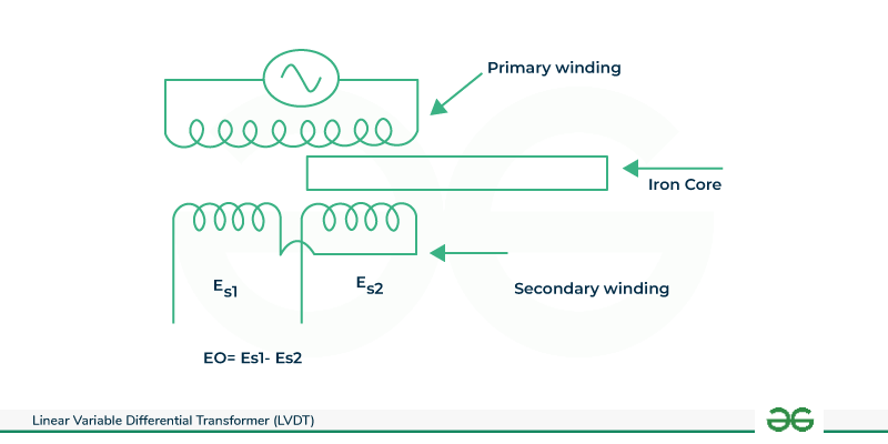
Case 1: When The Core is Moving Towards S1
When the core of LVDT moves towards the second winding S1 then the flux linkage S will be more as compared to S2. The EMF induced in S1 will be more than the EMF of S2. Hence E1 is greater than E & net differential voltage Eo(E1-E2) will be +ve. The means output voltage Vo will be in phase with input AC voltage.
Case 2 : When the core is positioned at its null position
When the core is at a null position then the flux generated in both the secondary windings will be the same. The induced EMF E1 & E2, and both the windings will be the same. Hence the net differential output voltage Eo will be 0. It shows 0 displacement of the core.
Case 3 : When The Core Moving Towards S2
When the core of LVDT moves towards secondary winding S2 then the flux linkage with S2 will be more than S1. It means the EMF induced in S2 will be more than the induced EMF of S1

LVDT in displacement
Hence E2 is greater than E1 & net differential voltage Eo (E1-E2) will be negative. It means the output voltage will be out of phase input AC voltage.
So in a nutshell we can conclude that the output of an LVDT is an AC voltage and the magnitude and other measurements of this output voltage provide insightful information about the direction and amount of displacement which is later inspected and fixed if any problem is detected.
Linear Variable Differential Transformers (LVDT) are mainly used for work or motion or movement in many industries and research, they are also used in medicine and patient monitoring similarly in many applications because of its ability of unique features and advantages. It offers high precision and accuracy as it has non-coated sensors it can also vary with measurement ranges like the miniature or subminiature LVDTs are suitable for applications with extremely limited space or where fine-scale displacement measurements are necessary. its versatile nature, Long term stability, and reliability are what make it useful and make it a preferred choice for displacement and position sensing in numerous applications.

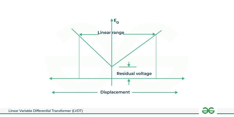
Show the displacement vs output voltage graph for movement in the right and left direction
Display the displacement versus output voltage graph for both left and right movement and how the output voltage varies with linear displacement.
The LVDT is an electromechanical device that generates an AC voltage output in direct proportion to the ferromagnetic core and relative displacement of the transformer . The ability of LVDT sensors to function in harsh environments with high levels of vibration and shock is a crucial feature.
As we can understand the Linear Variable Differential Transformer’s (LVDT) specifications can change based on the model and the requirements of the application. some common specifications of the LVDTs are:
Given Below are the Advantages and Disadvantages of LVDT:
So… in a nutshell, we can conclude that the Linear Variable Differential Transformer (LVDT) is a positional transducer that is widely used for many industrial as well as scientific applications. The model of LVDT is similar to the transformer. It is very precise and stable. The LVDT is more heavy-duty and strong because of its solid and simple design, which removes many possibilities of physical contact between the coils and core. The LVDT is very useful for applications that require accurate position sensing because of its highly linear and sensitive nature despite having a very simple structure. When all things are taken into account, the LVDT is a good option for industries like manufacturing, automotive, and aerospace where precise measurements are essential for flawless control and operation and LVDTs are highly repeatable due to their extremely low hysteresis etc benefits are there.
1. An AC LVDT (Linear Variable Differential Transformer) is characterized by the following parameters: Input = 6.3 V, Output = 3.2 V, and a range of ±0.5 inches. Determine the following:
Given that a 0.5-inch core displacement results in an output voltage of 3.2 V, a 0.45-inch core movement can be calculated as (0.45 * 3.2) / 0.5 = 2.88 V. Similarly, for a -0.30-inch core movement, the output voltage is determined as (-0.30 * -3.2) / (-0.5) = -1.92 V.
To find the output voltage for a -0.25-inch core movement, the calculation is (-0.25 * -3.2) / (-0.5) = -1.6 V.
The Linear Variable Differential Transformer (LVDT) sensors, can be used in the monitoring of cracks, for instance, in historical caverns in Israel by Hatzor et al .
Linear Variable Differential Transformers (LVDTs) are analog sensors that produce an output voltage based on the linear displacement of their core. Unlike digital devices, LVDTs themselves are not programmable in the traditional sense. They don’t have embedded processors or memory that allows for user programming.
Yes, LVDTs are often chosen for applications in harsh environments with high levels of vibration and EMI.